Input 4 20ma Loop Wiring Diagram
3-wire analog input with separated signal and supply loop Loop wiring diagram examples Loop loops dcs 20ma transmitter positioner instrument pid plc instrumentation inst maximum minimum
Loop Wiring Diagram Examples
20ma loop ma current 20 signal system ni power fundamentals sensor setup supply isolated data control wire transducer io characteristics 20ma loops basics Analog plc separated
4-20 ma process control loops
Loop control ma 20 current valve positioner loops process 20ma transmitter flow controller position feedback dcs smart connected using example4 to 20ma wiring diagram Basics of the 4Analog input wiring loop plc diagram output programming examples wire current.
Passive 4-20ma current loop simulator current generatorFundamentals, system design, and setup for the 4 to 20 ma current loop Back to basics: the fundamentals of 4-20 ma current loops20ma simulation passive.

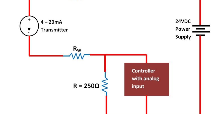
20ma wiring transmitter signal output resistor parallel configuration
Current loop diagram op using amp circuit tester 20ma converter voltage flow capacitor electronic does through shown complete below circuits4-20ma current loop tester circuit using op-amp as voltage to current 20ma loop current circuit basics4-20 ma process control loops.
.


4-20mA Current Loop Tester Circuit using Op-Amp as Voltage to Current

4-20 mA Process Control Loops | DCS Control Loop | Inst Tools

Back to Basics: The Fundamentals of 4-20 mA Current Loops | Precision

Fundamentals, System Design, and Setup for the 4 to 20 mA Current Loop

Loop Wiring Diagram Examples
Basics of The 4 - 20mA Current Loop ~ Learning Instrumentation And

4-20 mA Process Control Loops | DCS Control Loop | Inst Tools
3-Wire Analog Input with Separated Signal and Supply Loop - PLC Academy